How to Build Your Own CO2 Meter With an Adafruit Feather and E-Ink Display
Carbon dioxide levels have been a hot topic and in this tutorial I'll teach you how I made one from an Adafruit Feather, E-Ink display, CO2 sensor, and CircuitPython to help measure your air quality.

Overview
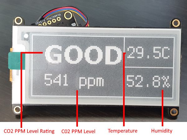
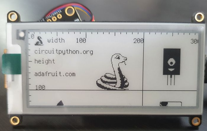
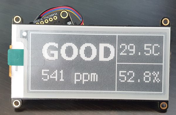
In this post you'll find my entire journey to get from components to hello world to a working project. It's a fun and amazingly simple little battery powered widget. Getting straight to the juicy bits, here's the final product:
With each area on screen:
All the code is on the GitHub repo:
 nikouu
Basic Plan
2021 onwards saw a surge of people using CO2 meters to help gauge indoor air quality. The Aranet4 seemed popular but I also saw people making their own and thought "that's a fun project, I'll do it too!"
On the 7th of February 2022 I penned up a quick sketch of an air quality sensor. Originally I wanted to use a Raspberry Pi Pico but found the eInk (I LOVE eInk) display I was looking at just instantly plugs into a Feather board.
The Raspberry Pi idea ultimately became another project around a motion detection wildlife camera with a Pi Zero 2 W, solar panel, and battery.
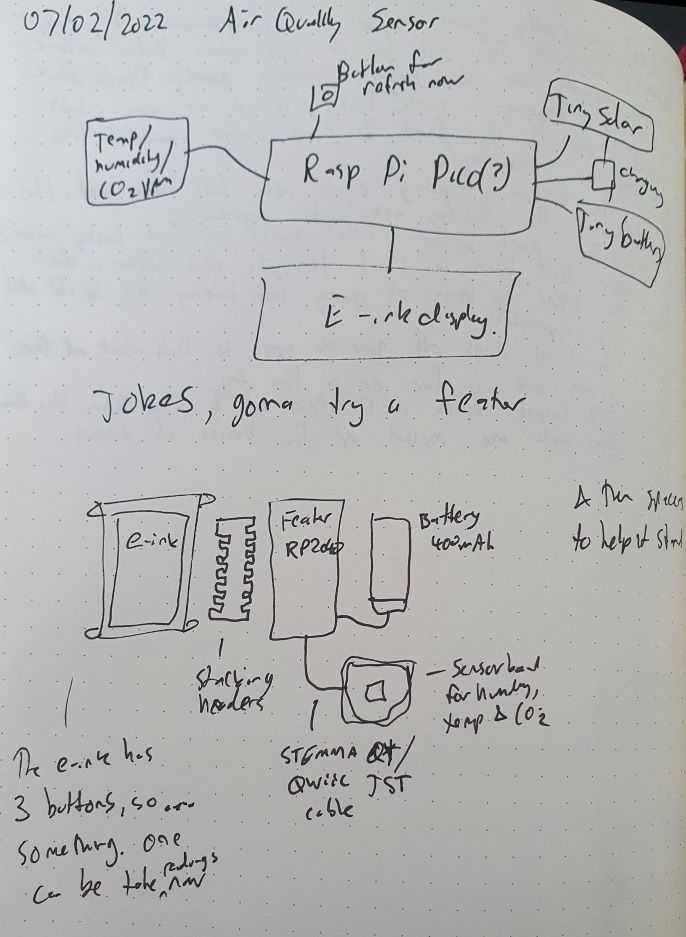
The original design was exactly what I ended up doing so let's jump into the components used.
Components
All components grabbed from Adafruit.
| Item | Cost (USD) |
|---|---|
| Feather RP2040 | $11.95 |
| Adafruit 2.9" Grayscale eInk | $22.50 |
| Lithium Ion Polymer Battery 400mAh | $6.95 |
| SCD-40 - True CO2, Temperature and Humidity Sensor | $49.50 |
| STEMMA QT / Qwiic JST SH 4-pin Cable | $0.95 |
| Brass M2.5 Standoffs 16mm tall | $1.25 |
| Total | $93.10 |
The only soldering needed is to attach the given headers onto the RP2040.
Development
Jump on board to scoot through the entire development cycle from "hello world" to "hel- oh no, I need to open a window".
Hello World
The Blink tutorial got me set up. Installing the Mu Editor, going over basics of setting up the Feather, and of course the first "hello world" code (blinking an LED). FYI that the LED blinking isn't the fancy RGB NeoPixel.
Running the Display
Adafruit have a great tutorial specifically for the 2.9 inch greyscale eInk display:
 Melissa LeBlanc-Williams
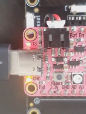
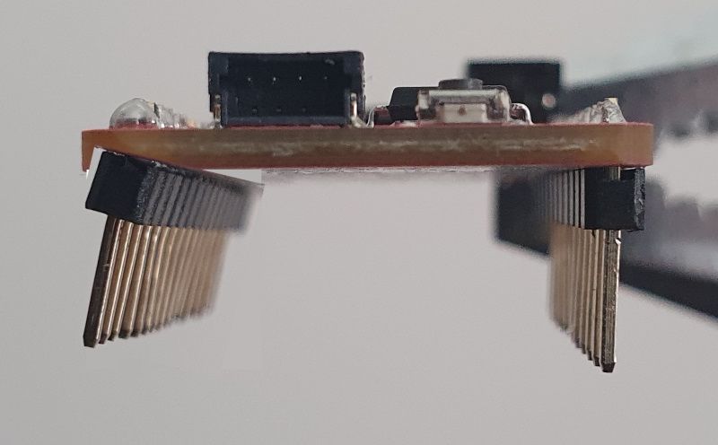
First up is soldering the header pins included with the RP2040 so I can connect it to the eInk FeatherWing. It had been a hot minute since I last soldered, and the wonk-factor made this painfully obvious. Since there's no evidence, here's a dirty edit of what the pins looked like before correcting:
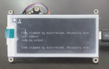
I jammed in the Feather into the back of the display and excitedly executed the tutorial code aaaaand...
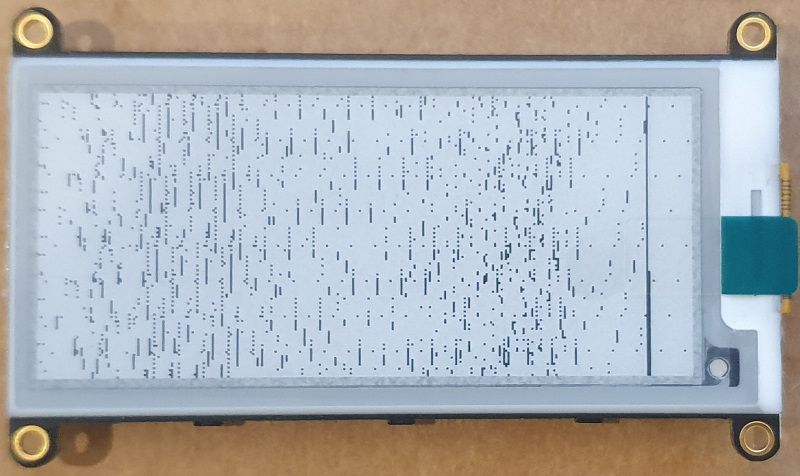
That's on me 🤚 since I misread the tutorial and copied the code for a different eInk display 🤦♀️
Once I sorted out the very basics of reading comprehension, the default tutorial image displays!
For drawing shapes I stole took inspiration from a CircuitPython file relating to the MagTag eInk product:
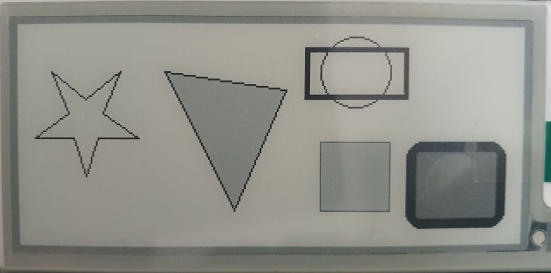
With an understanding of how to manipulate the display, it's time to do the CO2 readings.
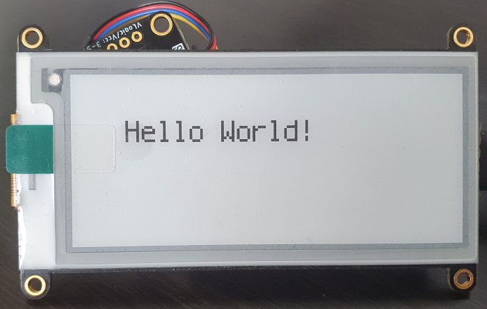
Displaying Text
Displays "Hello World!" on the display. Nothing too much here.
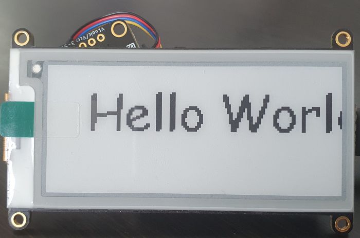
Displaying Text with a Different Font
But what if we used a different font 🤔
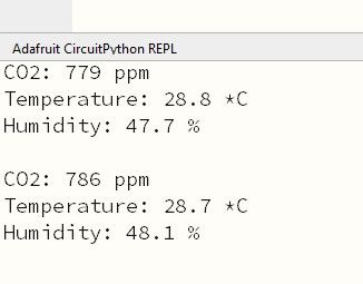
Getting the CO2 Values
I'm loving how the tutorials are easy to find and the tutorial for the SCD-40 is no exception. The sample code is easy and it showed up exactly as expected in the Mu editor serial output window.
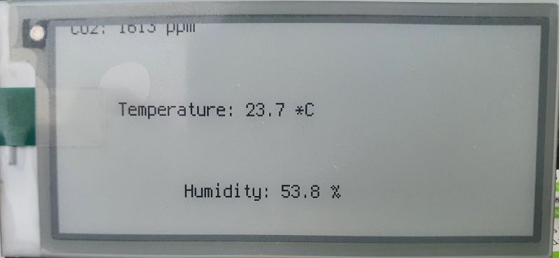
Proof of Concept
Bringing together most of the above, we can get the sensor information on screen!
Version 1.0 - First Stable Release
Taking the previous milestones and making it presentable. This now pulls together all the previous work.
It runs as intended with a 🎵simple and clean🎵 UI. Slightly cryptic if you didn't know what the SCD-40 reads, but good enough for now. It updates every 4.5 minutes. Note the display should only be refreshed every 3+ minutes to prevent damage.
The code itself is pretty easy and reads something closer to a Bash or Powershell script. I could've probably made it more OO but I think there's some romance (sure, let's go with that) in having it a simple to understand, cobbled together script. Makes me nostalgic for the old days.
The ratings you see on screen are based off the first few results when searching for CO2 levels. Some articles seemed very rooted in science, and others felt more general. The most definitive piece I saw was that less than 800ppm was pretty good.
Below is a gallery of what the little device looks like:
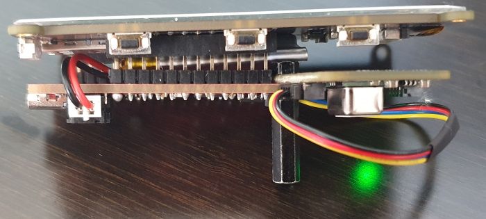
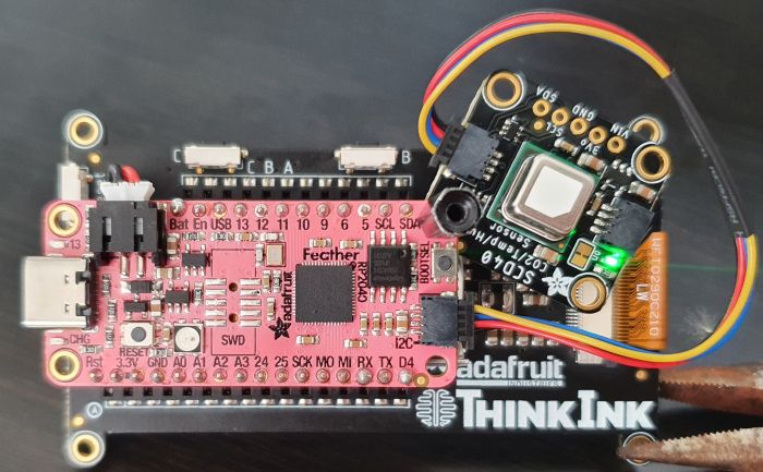
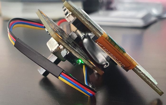
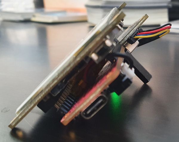
There is no case and sensor itself is free to hang with just one corner bolted. Actually that single spacer to hold the sensor to the RP2040 together being used as a makeshift kickstand works pretty well!
Since we haven't seen them yet - a preview of other CO2 ratings (with expertly consistent photography):
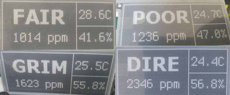
From the pictures above it's obvious that nothing is properly centered on the display. No pixel counting nor proper usage of a centered anchor for the text is in play.
With the stable release out of the way, it was time to begin working on improvements on power consumption. Having worked a little bit with Raspberry Pi Zero 2 W boards and looking at power usage, I figured this microcontroller without a proper OS must get a lot out of the 400mAh battery but it didn't... At first.
Oh side note: about 3 hours for a full charge. I charge it using either a regular phone charger or from my computer.
Version 1.2 - Improved Power Efficiency
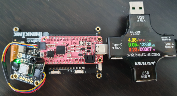
The 400mAh battery lasts (very) approximately 12 hours with the first stable release and I think it can do far better. But first, let's understand the power usage patterns. I'll be using a Multifunctional USB Digital Tester - USB A and C to take the readings, with several baselines:
| Scenario | Description | Reading | Notes |
|---|---|---|---|
| Baseline 1 | Blinking LED, nothing attached | 0.21W-0.23W | Our absolute baseline |
| Baseline 2 | Blinking LED, display attached (nothing displaying) | 0.21W-0.23W | |
| Baseline 3 | Blinking LED, display attached (nothing displaying), SCD-40 (nothing reading) | 0.21W-0.25W | |
| Baseline 4 | Stable release code v1.0 | 0.23W-0.74W | Big spikes (more on that below), otherwise about the same as previous scenarios |
Now that we have baseline measurements, it's time to optimise!
Version 1.1 - Deep Sleep
Let's deal with the easy stuff: Busy waits. I love optimising things (self plug: Shrinking a Self-Contained .NET 6 Wordle-Clone Executable) and there's a whole heap of ways for programs to sleep across different languages. I suspect that in CircuitPython that the time.sleep() call might be a bit busy in the background.
Doing some digging, it turns out we can use alarms instead of sleeps. I picked up on this fantastic tutorial called Deep Sleep with CircuitPython which explained the different types of sleep in CircuitPython.
I ran some tests (which are in the Tutorials/DeepSleep folder) for sleep types. The test case was a blink based on the tutorial and here are the results:
| Scenario | Description | Reading | Notes |
|---|---|---|---|
| Sleep 1 | time.sleep() |
0.21W-0.23W | This one is in the Blink folder |
| Sleep 2 | alarm.light_sleep_until_alarms() |
0.17W-0.25W | But more often around 0.17W-0.23W |
| Sleep 3 | alarm.exit_and_deep_sleep_until_alarms() |
0.11W-0.23W | Both:
|
Note: Test when connected to a power supply, and not PC as the board will not actively sleep when connected to a host computer.
The deep sleep looks like what we want. So let's apply it to the stable release:
| Scenario | Description | Reading | Notes |
|---|---|---|---|
| Efficiency 1 | Stable release code with improved power efficiency | 0.13W-0.64W | A good improvement but with the same big spikes (see version 1.2) |
A ~0.1W drop and the spikes remain.
This version, version 1.1, the battery lasts about 21 hours. Or 1.75 time longer than version 1.0.
Version 1.2 - Turning off the Sensor
Spike time. Every 3-5 seconds as it seems the SCD-40 sensor does a reading regardless of whether the values are read. Below is a quick look at the meter, note the red wattage reading on the lower left and how it spikes:
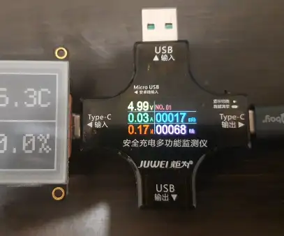
Note: The display on the reader presents averages between updates. It may not show the proper spike on each display update due to this.
Notice that these spikes did not happen in scenario Baseline 3 (from further up on this page) even with the sensor connected - it only started happening in Baseline 4 when the sensor has been activated. We can prove this by using the same blink code as Baseline 1, but added in the start measurement code for the sensor from Baseline 4:
import time
import alarm
import board
import digitalio
import adafruit_scd4x

led = digitalio.DigitalInOut(board.LED)
led.direction = digitalio.Direction.OUTPUT

i2c = board.I2C()
scd4x = adafruit_scd4x.SCD4X(i2c)
scd4x.start_periodic_measurement()

while True:
    led.value = True
    time.sleep(1)
    led.value = False
time.sleep(3)| Scenario | Description | Reading | Notes |
|---|---|---|---|
| Baseline 5 | Blinking LED, no display attached, SCD-40 activated | 0.23W-0.71W |
Nailed it. Confirmed that the sensor measurements need to be kicked off before we see the power usage spikes - not just having the sensor connected to the board.
In theory if there is a start then there should be a stop. And there is! stop_periodic_measurement() is the exact call we're looking for. So the code will now:
- Only start a measurement just before needing the value
- Read and store the result
- Immediately stop the measurement
Let's see what that looks like:
| Scenario | Description | Reading | Notes |
|---|---|---|---|
| Efficiency 2 | Efficiency 1 + power spike removal | 0.11W-0.15W | Then with the spike to 0.71W at the 5 minute mark to do a single read |
After these improvements, the battery now lasts 54 hours, or 4.5 times longer than the version 1.0.
Future Ideas
Maybe these would be neat to implement, maybe they won't. Maybe they've been implemented far after this post's been written 🔮
- Use the eInk display buttons to switch to a graph mode
- Add symbols to help define what each reading is
- Properly center all the elements
- Make use of the four greyscale colours
- Take readings every x amount of time between display refreshes to get an average
- Have a button push to refresh asap (as soon as it's been 3 mins since the last display refresh)
- Battery indicator
- A way to tell whether the battery has run out on the display (currently the green LED on the sensor is the only indicator)
Conclusion
This was a friendly project to do - I thought it was going to be much more difficult. The mixture of (mostly) no soldering, easy to grasp examples, and CircuitPython reduced the faff and got me right into a good mood for programming.
It's also changed my behaviour around opening windows at home and given me an idea of my workplace air quality. A practical project feels really fulfilling, yaknow?
I hope you found this useful and this post maybe even gave you a smidge of inspiration to make your own air quality sensor or other Feather project.
Thanks for reading!